

How to connect the Beninca VN.MT20/MT40 engine to the eL17 controller
Connecting the Beninca VN.MT20/MT40 engine to the eL17 controller
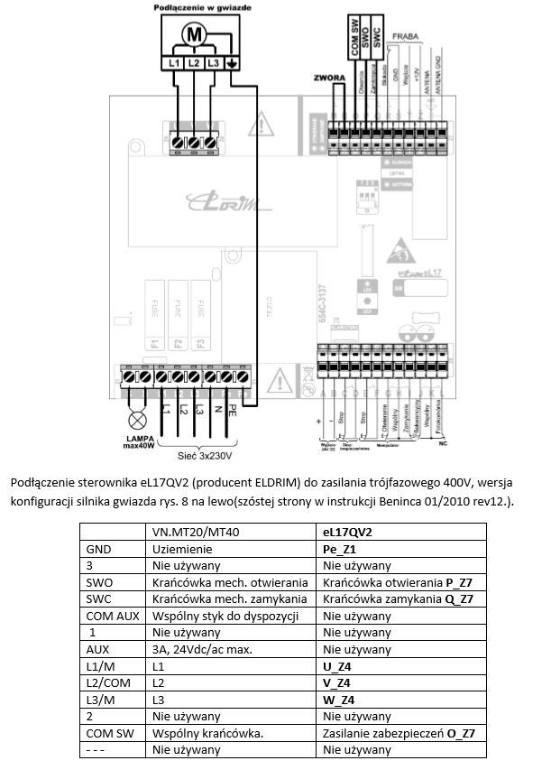
Connecting the Beninca VN.MT20/MT40 engine to the controller eL17QV2 (producer ELDRIM) for three-phase 400V power supply, star motor configuration version Fig. 8 on the left (on the sixth page in the Beninca manual 01/2010 rev12.)
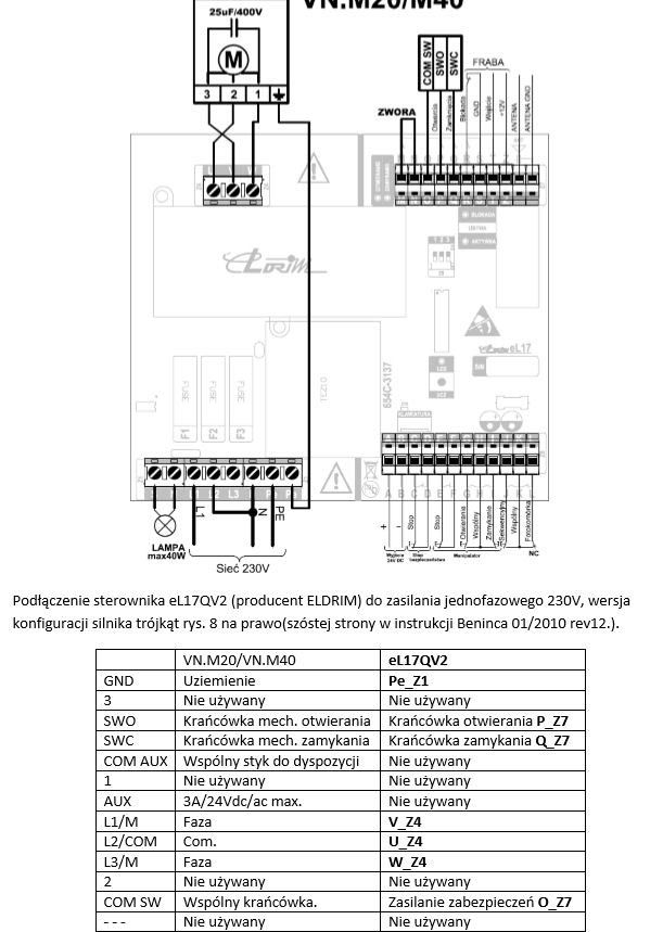
Connecting the eL17QV2 controller (manufacturer ELDRIM) to a single-phase 230V power supply, triangle motor configuration version, Fig. 8 on the right (page six in the Beninca manual 01/2010 rev12.).
To connect the Beninca VN.MT20/MT40 motor to the eL17 controller, please follow the instructions provided by the manufacturer. Here are the general steps for you to make this connection:
Preparation of tools and materials:
- Screwdriver
- Electric cables
- Cable processing tools
- Operating instructions for the VN.MT20/MT40 engine and eL17 controller
Power off:
- Before starting any work, make sure the power is turned off to avoid the risk of electric shock.
Connecting the cables:
- Identify terminals: Read the markings on the terminals on both the motor and controller. User manuals should include connection diagrams.
- Connect the wires: Connect the cables according to the diagram provided by the manufacturer. Below is an example connection diagram, which may vary depending on the specific model and software version:
- Connect the power cables (L and N) to the appropriate terminals on the eL17 controller.
- Connect the cables from the VN.MT20/MT40 engine to the appropriate terminals in the eL17 controller. Most often, these will be terminals marked "MOTOR" and wires for endstops.
- Connecting accessories:
- If you have additional accessories, such as photocells, control buttons or other safety devices, connect them in accordance with the eL17 controller user manual.
- Check connections:
- Make sure all connections are secure and in accordance with the user manual.
- Check whether the cables are properly secured to avoid mechanical damage.
- Power on and testing:
- Turn on the power to test the system operation.
- Make sure the gateway operates smoothly, without interruption and as expected.
- Calibration and programming:
- If necessary, calibrate and program the eL17 controller in accordance with the operating instructions. This may include setting limit switches, opening/closing speeds and other operating parameters.
In case of difficulties or doubts, it is always worth contacting the manufacturer's technical service or commissioning the installation to a qualified specialist. Remember that proper connection and configuration are crucial for the safe and reliable operation of your gate automation system.

